Update: I have uploaded a YouTube video of the testing process http://www.youtube.com/watch?v=BX8UoTgS50M
First tests and calibration
- Power connected and turned on (cooling fan for stepper drivers going), and USB cable connected
- Arduino software - you need this to compile and upload your firmware. Go back The Basics and read/re-read what I already typed out Arduino installation, no point in copy and paste.
- Host software - you'll need Repetier, Pronterface, or Cura software next. I use Repetier host.
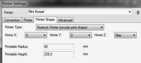 |
| Repetier-Host Printer Shape |
In addition, you need to tell Repetier-host to home to X=0, Y=0, and Z=MAX (click the Printer Shape photo to zoom in).

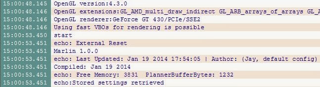
 Click the Connect button and it should turn green. Click the Manual control tab and if you don't see the Log window click the Toggle Log button. there should be a simple message about the version of Repetier FW in the log.
 |
| Log output in Repetier-host at start |
Check end stops
You should see something like: (L = logic low = connected to ground)
18:34:03.532 : N63 M119 *63
18:34:03.551 : x_max:L y_max:L z_max:L
Now one at a time push and hold an end stop switch and rerun the M119 command (hint, you can press the up arrow key on your keyboard to cycle through the history of G-Code commands you have issued via the G-Code entry field). You should see L changed to H for the matching endstop. If not, then there is a wiring issue (make sure you plug max X(alpha) endstop into X+ not Y+ or Z+ :) Do not continue until you get this right. Test all 3 endstops.
Note: If you have a probe (and I don't think you need one) then make sure it shows H when retracted and L when deployed.
Check motor direction (Note: deltas use a blend of all 3 motors to move the effector)

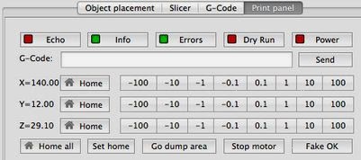 |
| Notice the Mac manual controls are not a graphic like Windows. |
Let's start with Y. Click the 1mm in the Y+ direction, the effector should move to the rear toward the Z(gamma) tower. If not, take notice of which way each carriage moved, X(alpha) should have moved down, Y(beta) moved down, and the Z(gamma) carriage up. If any of these moved opposite, STOP (never unplug a stepper motor while it's powered, you will destroy the stepper driver), unplug
the 12V power, and flip the stepper connector on the ramps for that motor. Then you can reapply the 12V power. Repeat until they move as they should. Now same for X, click the 1mm in the +X direction and make sure the effector travels to the right. If that looks good then Try the Z+ 1 mm and all 3 should move up. If all these work, then it's time to home.
Home (Note: make sure in your EEPROM setting you set the Homing feedrate [mm/s] to something reasonable like 90 to start)
 Keep one hand on the power cord (emergency disconnect), the reset on the RAMPS, or better yet the power switch if you wired on in, for the first time and go ahead and remove your build plate or put something to protect it ;) Ok, now click any of the home buttons, there are 4, (keep in mind host software was designed for Cartesians. For delta all axis will home at the same time). All carriages should move up at the same speed (the homing speed) until they hit their end stops. Then the X(alpha), followed by Y(beta) and finally Z(gamma) will home and back off the switch. Congratulations! If not, then you skipped a step and hopefully nothing was damaged. Go back to the basics or wiring and confirm you got it right.
Calibration (Note: This link to Calibrating a 3D Printer is the de facto set of instructions for this, i only disagree with where he says you need to disable EEPROM.)
 Now comes the arduous task of calibrating your actual MANUAL_Z_HOME_POS as well as your Tower X/Y/Z endstop offset. Before we begin, I think it's worth understanding what we are trying to do and what endstop offsets do for us.
In order to print thin layers and have successful first layer adhesion we need to make sure the effector (and the hotend it carries) moves parallel to our build surface and is calibrated such that Z=0 means the tip of our hotend is touching the build surface at any point. We also need to make sure our build surface is "flat" from one point on its surface to any other point. I put flat in quotes because depending on your layer thickness, 0.1mm maybe flat enough. The design of the delta with the 3 sets of parallel arms is such that it should constrain the movement effector to remain flat and not tilt or rotate around the X or Y axis. If you notice any tilting in your effector (or nozzle tip) then your arms are not parallel, not fixed to the pivot points (magnets?), or not the same length and this is a physical issue, not software.
The firmware has to convert a set of coordinates into the number of steps for each axis motor. This is some Pythagorean math (A^2 + B^2 = C^2) and is calculated for each tower, for each move, and moves are subdivied by segments per line so there is a lot of computations. In order to move where we want, the machine needs to have a reference point to start from. We call it Home, and on most deltas it's chosen to be at the maximum (max) or top of the machine. The trick is, how to you ensure that each axis endstop is in the exact same location, such that when you are homed ( X0 Y0 ZMAX_Z), the effector is in the center of the machine, and when you are at X0 Y0, Z0 the effector is still in the center and each axis has moved Z_MAX in distance and the tip of your hotend is just touching the build surface? On some designs the endstop is fixed (3DR, Lisa) and thus is guaranteed to be at the same height. Other designs have a mechanical adjustment to allow one to tweak the end stops.
The mini Kossel does not have physical adjusters and they are implemented in the firmware. In Repetier FW, you use the Tower X/Y/Z endstop offset variables to specify the number of steps to move away from the endstop after homing. The Tower X/Y/Z endstop offsets are positive integers since the logic already knows you are moving away from the endstop toward the build surface.
You should test your MAX_Z before you send a command to go to Z0. I would advise you sneak up on the distance to the build surface as you move the nozzle down to Z0. If you reach the surface before Z = 0.0 then you need to subtract the value Z displays from your MANUAL_Z_HOME_POS, just change the value in the EEPROM configuration window. The Max Z height will change in the next steps so don't worry about getting it perfect, we are just trying to get close on the first round.
Step 1, we need to make sure that each axis carriage is at the same height after homing. To do this, we need to home the machine (send a G28 G-Code command or click any home button). Then send a G-code command to get the nozzle at a point on the surface directly in front of each axis (X, Y, Z in that order). The nozzle should be touching such that if pinches a piece of paper, but that paper can be pulled out from between the nozzle and surface without tearing. So let's look at the three outcomes for each trial. Here are our starting conditions (my comments in red)
- steps per mm are 80
- Tower X/Y/Z endstop offset are all 0 (start with no endstop offsets)
- MANUAL_Z_HOME_POS 225.0 (determined from step 1)
- Build radius = X_MAX = Y_MAX = 85 (for a build diameter of 170mm)
- Horizontal radius = 105 (use visual calculator to get this)
- Or use the rough assumption that the diagonal rod will be at 60 degrees when homed and so the formula cos(60) = Horizontal radius/Diagonal rod -> Diagonal rod/2
- The coordinates for the point in front of the X/Alpha tower are
- X=(Build radius)COS(210) Y=(Build radius)SIN(210) Z0
- X=-73 Y =-45
- G1 X-73 Y-42 Z5 F6000 (start at 5mm above the surface and step down to Z0 in 1mm then 0.1mm increments and move there at 100mm/s)
- Pay attention to the axis readouts on the Manual Control tab, especially the Z value
- The nozzle pinches the paper and it can just be pulled out when Z=0. This is the ideal state and means you can move to the next axis (Y/Beta). If you get this on the first try you got lucky :)
- The nozzle is above the surface (let's say by 2mm) when Z=0. This means we need to increase the offset for this axis by at least 2mm and I usually go 1mm more (Hint: Richard Turnrock has suggested to use a pad of Post-it notes as a variable feeler gauge. ) so I can get a more accurate sub-millimeter value. We need to multiply the distance by the steps per mm (3 * 80 = 240) and set the Tower X offset [steps] to 240. Send a G28 (home), then send G1 X-73 Y-42 Z2 F6000 which should put you roughly 1mm above the surface. Use the Z -0.1 button to step down while testing with a sheet of paper as your feeler gauge. If you reach a point where there is sufficient drag of the nozzle on the paper and Z value showssomething other than 0, then subtract that amount from the X offset value in EEPROM. Let's say Z = 0.4, then subtract 0.4*80 = 32 from 240 and update to 208 in the EEPROM configuration. Once again send G28, then G1 X-73 Y-42 Z0 F6000 and confirm the paper test works.
- The nozzle reaches the surface before Z=0. In this case, you will need to physically move the plastic piece that holds the end stop up. or you can reduce your MANUAL_Z_HOME_POS then re-home (G28) and retest.
Once you finish X/Alpha, then move on to Y/Beta. Once you finish Y/Beta, Check X/Alpha and adjust if needed. If you adjust X/Alpha, then recheck Y/Beta. If X/Alpha and Y/Beta are good, go on to Z/Gamma. And you guessed it, once you finish Z/Gamma, check and adjust the other two as needed.
Step 2, ok now all 3 carriages are at the same height and pass the paper test. Now we need to set the center. If Horizontal radius is not accurate then your nozzle may be above or hitting the surface (trying to move through it) at Z0. Again to preserve your machine, use a G1 X0 Y0 Z5 F6000 to sneak up on Z0.
- If the nozzle passes the paper test at Z=0 then you are done.
- If the nozzle is above the surface and Z=0 then you need to increase Horizontal radius. As soon as you do, you'll need to go back through step 2 (The difference this time is you should have to add the same amount of offset to all three. ). How much you change it depends on how far off it was. You can try 1mm at a time and increase by more or less depending on the observed change.
- If the nozzle touches the plate before Z=0, then you'll need to decrease Horizontal radius and go back through step 1 and step 2.
Step 3, you should have very parallel movement now, and any point you chose on the surface should pass the paper test at Z=0. Don't forget to update your host software's Printable Height in the Printer Settings. Now you need to calibrate your extruder steps. The de facto on that is Triffid Hunter's Calibration Guide. I was recently given the tip to use 1/8th microstepping instead of 1/16th as a way to increase my retract speeds. I have a 5.2:1 geared stepper and this allowed me to go from 35mm/s to 70mm/s which makes a difference. However, that resulted in a little more vibration which meant more noise so I'm looking for more sound isolation opportunities.