Sunday, March 2, 2014

New printer, do as I say, not as I do.

New printer

I just finished building a new mini Kossel. This one I designed using my visual calculator Excel spreadsheet and decided to use 10" or 254mm horizontal pieces instead of 240mm. This was because I wanted a slightly larger build area of 125mm square. I also wanted to use printed sliders instead of rail guides. If you follow my Youtube channel you'll know that I was experimenting with these. Well here is the proof that they work for a printer too. Here is the Thingiverse thing for the sliders.

The endstops are not mounted on a plastic piece. I found some #4 screws and matching nuts in my bin. The 2mm nut has enough width to span the extrusion, so the endstops are mounted directly to the extrusion. The wires are routed down the inner "track" of the extrusion which is the only side of the slider that I left open. The other three sides have a "rail" that rides in the "tracks".
Otherwise, the printer uses all of the same parts as my other mini. Well, that's not true. I bought the screw kit from tridprinting.com for my first mini. Since then, I've been buying extra screws via Amazon from Small Parts. I have purchased 6mm, 8mm, 10mm, 12mm, 16mm, and 20mm stainless M3 screws in boxes of 100 (anywhere from $3.50 to $6.75). Since I had so many 20mm, I decided to use those wherever I could in place of the 35mm ones. I still needed 3 35mm screws for the top bearings, and fortunately I had 3. I did have to redesign the effector to make the net traps deeper to use the 20mm there, but the carriages worked as is.  I'm also using the 40mm silent fan I like so much like my other printer.

I don't have an extruder for it just yet, so I'm using the one from my Prusa. I'm running a 3mm setup for this printer. So far, it oozes a bit more at idle, but the print quality is excellent, and no strings anywhere.

The short of it

I have spent the last two days finishing my new mini Kossel and running through the First Calibration and testing. I wanted to video the process so others could see what I was doing. I did video the process, but man did I screw it up royally on my configuration settings. Keep reading to find out how it unfolded.

The long of it

I started out using the calculated values from my mini Kossel calculator/visual calculator. My delta diagonal rods were built using a jig and set to be 220mm pivot to pivot. The calculator gave me 112.6mm for the Horizontal radius (Delta radius for Marlin), and I see all 3 tower offsets to 0. I went through 3 rounds and finally got the 3 positions in front of the towers to Z=0 and the center. However, when I tried the other 3 positions they were off (one was low, another high). I scratched my head, and proceeded. WHAT? Yep without having a valid explanation I plowed on.

I started with a simple calibration object, 20mm ID, 22mm OD, 1mm solid, and 1mm hollow for a total hight of 2mm. The measurements were too big, 22.75 ID, 24.8 OD, and 2.54 tall. The voice in my head was screaming TOO BIG, THE DIAGONAL IS 220, IT CAN'T BE ANYTHING ELSE ... but I ignored it, and proceeded to modify both the diagonal rod length, and the horizontal length. INSANE! Yes I know. After another 6 rounds of calibration (no I didn't film these), I got all 4 spots dialed in. The other 3 were still off, but I plowed ahead. This time the print was closer in X and Y, but the Z was still 2.54mm. The only thing that controls Z is the steps per mm. It's set to 200. 1/32nd stepping, 200 steps per, GT2 belts and 16....OH @#$%$#$ ... NOT 16 TOOTH PULLEYS, 20 TOOTH. So not 200, 160.

Oh yeah, I had copied my other mini Kossel Repetier firmware over and neglected to change the settings. Not only that, but I never bothered to check/confirm my print surface radius, or look to see if 10mm was moving 10mm with my steel rule. UNBELIEVABLE ... or not. I was in such a rush to get to the good stuff, that I neglected my own advice.

Back to Square 1

I reset everything, diagonal rod to 220, horizontal radius to 112.6, and all 3 tower offsets to 0. I then measures the Z max with my steel rule and could estimate 242mm build height. After several rounds I ended up with a horizontal radius of 113.5 and a Z_Max of 245mm. And all 7 spots on the build surface wer dead on. So I fired up the hotend and printed another test square. This one was accurate, so I decided to print a mini Kossel top vertex as a real test. It came out dimensionally accurate (15mm tall, the holes were 3mm, etc...) but the infill was too low. Yep I admit it, I had not calibrated my extruder :/

After finishing the extruder calibration, this is what the print came out like.

The one on the left is showing that the 1515 extrusion fits like a glove (15.01mm) as well as the top infill. The second is showing the bottom and how perfect the 3mm nut is captured. I would say this calibration is 100% and I can start printing new sets to distribute.


Wednesday, February 26, 2014

First tests and Calibration - Repetier Firmware

I originally wrote this post, and geared it toward the firmware I was using at the time, Marlin. I then tried to edit the post and added Repetier firmware (FW will be use for firmware for the rest of the post) notes. User feedback says it would be better to have one for Marlin, and one for Repetier FW.

Update: I have uploaded a YouTube video of the testing process http://www.youtube.com/watch?v=BX8UoTgS50M

First tests and calibration

  1. Power connected and turned on (cooling fan for stepper drivers going), and USB cable connected
  2. Arduino software - you need this to compile and upload your firmware. Go back The Basics and read/re-read what I already typed out Arduino installation, no point in copy and paste.
  3. Host software - you'll need Repetier, Pronterface, or Cura software next. I use Repetier host
Repetier-Host Printer Shape
Open your host software and configure your port. Arduino creates a com (communications) port and that's what you'll want to use. You can leave the port and the baud at auto and let the software auto-detect these. Now we need to configure the printer setting in the host software. This should match your firmware. Repetier-host lets you specify your printer is a Delta and will change the display to show a cylindrical print volume with the origin point at (0,0,0), other hosts may or may not doe this. Follow the configuration guide and use -85 and 85 (or whatever the radius of your print surface is) for the X and Y minimums and the same MANUAL_Z_HOME_POS value you used in firmware.

In addition, you need to tell Repetier-host to home to X=0, Y=0, and Z=MAX (click the Printer Shape photo to zoom in).


Click the Connect button and it should turn green. Click the Manual control tab and if you don't see the Log window click the Toggle Log button. there should be a simple message about the version of Repetier FW in the log.

Log output in Repetier-host at start

Check end stops
Before you click home(the 12V power should be off or you can click the "Turn Motors Off button or send M84 gcode commandmanually move your effector down until all three max end stops are not touching. Now lets check a few things otherwise you may get an unpleasant surprise. In the G-Code: text box type M119 and click Send (or press enter).
You should see something like: (L = logic low = connected to ground)
  18:34:03.532 : N63 M119 *63
  18:34:03.551 : x_max:L y_max:L z_max:L

If not, then something is miswired or misconfigured. Confirm that you connected to NC (normally closed) and C (common) on the switch, and you connected the two wires to the X+Y+, and Z+ pins on the RAMPS, and those two wires connect to the S (signal) and - (ground) pins, not the (5V). Another reason would be you did not update and upload the configuration.h changes I discussed in The Basics.  NoteIf you connected to the normally open NO instead, then you will need to invert the logic in the configuration.h (#define ENDSTOP_X_MAX_INVERTING true // instead of false)

Now one at a time push and hold an end stop switch and rerun the M119 command (hint, you can press the up arrow key on your keyboard to cycle through the history of G-Code commands you have issued via the G-Code entry field). You should see L changed to for the matching endstop. If not, then there is a wiring issue (make sure you plug max X(alpha) endstop into X+ not Y+ or Z+ :) Do not continue until you get this right. Test all 3 endstops.
Note: If you have a probe (and I don't think you need one) then make sure it shows when retracted and when deployed.

Check motor direction (Note: deltas use a blend of all 3 motors to move the effector)
If everything checks out so far, then we need to confirm the motors are moving in the right direction. Again, disable the motors and manually move the effector down so it's around 100mm away from your surface. On the Manual Control tab, use the X and Y arrows to manually move the end effector. The arrows are divided into segments. The segment closest to the center will move the effector in that direction 0.1mm. The next segment 1mm, then 10mm then 50mm. Z only has the 0.1mm, 1, and 10 segments. Mac users, the author decided to give you a row of buttons from -100 to 100 for each axis. Remember we home to the Max and so all movements toward the bed are negative.
Notice the Mac manual controls are not a
graphic like Windows.

Let's start with Y. Click the 1mm in the Y+ direction, the effector should move to the rear toward the Z(gamma) tower. If not, take notice of which way each carriage moved, X(alpha) should have moved down, Y(beta) moved down, and the Z(gamma) carriage up. If any of these moved opposite, STOP (never unplug a stepper motor while it's powered, you will destroy the stepper driver)unplug 
 the 12V power, and flip the stepper connector on the ramps for that motor. Then you can reapply the 12V power. Repeat until they move as they should. Now same for X, click the 1mm in the +X direction and make sure the effector travels to the right. If that looks good then Try the Z+ 1 mm and all 3 should move up. If all these work, then it's time to home.


Home (Note: make sure in your EEPROM setting you set the Homing feedrate [mm/s] to something reasonable like 90 to start)
Keep one hand on the power cord (emergency disconnect), the reset on the RAMPS, or better yet the power switch if you wired on in, for the first time and go ahead and remove your build plate or put something to protect it ;) Ok, now click any of the home buttons, there are 4, (keep in mind host software was designed for Cartesians. For delta all axis will home at the same time). All carriages should move up at the same speed (the homing speed) until they hit their end stops. Then the X(alpha), followed by Y(beta) and finally Z(gamma) will home and back off the switch. Congratulations! If not, then you skipped a step and hopefully nothing was damaged. Go back to the basics or wiring and confirm you got it right.

Calibration (Note: This link to Calibrating a 3D Printer is the de facto set of instructions for this, i only disagree with where he says you need to disable EEPROM.)
Now comes the arduous task of calibrating your actual MANUAL_Z_HOME_POS as well as your Tower X/Y/Z endstop offset. Before we begin, I think it's worth understanding what we are trying to do and what endstop offsets do for us.

In order to print thin layers and have successful first layer adhesion we need to make sure the effector (and the hotend it carries) moves parallel to our build surface and is calibrated such that Z=0 means the tip of our hotend is touching the build surface at any point. We also need to make sure our build surface is "flat" from one point on its surface to any other point. I put flat in quotes because depending on your layer thickness, 0.1mm maybe flat enough. The design of the delta with the 3 sets of parallel arms is such that it should constrain the movement effector to remain flat and not tilt or rotate around the X or Y axis. If you notice any tilting in your effector (or nozzle tip) then your arms are not parallel, not fixed to the pivot points (magnets?), or not the same length and this is a physical issue, not software.

The firmware has to convert a set of coordinates into the number of steps for each axis motor. This is some Pythagorean math (A^2 + B^2 = C^2) and is calculated for each tower, for each move, and moves are subdivied by segments per line so there is a lot of computations. In order to move where we want, the machine needs to have a reference point to start from. We call it Home, and on most deltas it's chosen to be at the maximum (max) or top of the machine. The trick is, how to you ensure that each axis endstop is in the exact same location, such that when you are homed ( X0 Y0 ZMAX_Z), the effector is in the center of the machine, and when you are at X0 Y0, Z0 the effector is still in the center and each axis has moved Z_MAX in distance and the tip of your hotend is just touching the build surface? On some designs the endstop is fixed (3DR, Lisa) and thus is guaranteed to be at the same height. Other designs have a mechanical adjustment to allow one to tweak the end stops.


The mini Kossel does not have physical adjusters and they are implemented in the firmware. In Repetier FW, you use the Tower X/Y/Z endstop offset variables to specify the number of steps to move away from the endstop after homing. The Tower X/Y/Z endstop offsets are positive integers since the logic already knows you are moving away from the endstop toward the build surface.

You should test your MAX_Z before you send a command to go to Z0. I would advise you sneak up on the distance to the build surface as you move the nozzle down to Z0. If you reach the surface before Z = 0.0 then you need to subtract the value Z displays from your MANUAL_Z_HOME_POS, just change the value in the EEPROM configuration window. The Max Z height will change in the next steps so don't worry about getting it perfect, we are just trying to get close on the first round.

Step 1, we need to make sure that each axis carriage is at the same height after homing. To do this, we need to home the machine (send a G28 G-Code command or click any home button). Then send a G-code command to get the nozzle at a point on the surface directly in front of each axis (X, Y, Z in that order). The nozzle should be touching such that if pinches a piece of paper, but that paper can be pulled out from between the nozzle and surface without tearing. So let's look at the three outcomes for each trial. Here are our starting conditions (my comments in red)
  • steps per mm are 80
  • Tower X/Y/Z endstop offset are all 0    (start with no endstop offsets)
  • MANUAL_Z_HOME_POS 225.0 (determined from step 1)
  • Build radius = X_MAX = Y_MAX = 85 (for a build diameter of 170mm)
  • Horizontal radius = 105 (use visual calculator to get this)
    • Or use the rough assumption that the diagonal rod will be at 60 degrees when homed and so the formula cos(60) = Horizontal radius/Diagonal rod -> Diagonal rod/2
  • The coordinates for the point in front of the X/Alpha tower are 
    • X=(Build radius)COS(210) Y=(Build radius)SIN(210) Z0
    • X=-73 Y =-45
  • G1 X-73 Y-42 Z5 F6000  (start at 5mm above the surface and step down to Z0 in 1mm then 0.1mm increments and move there at 100mm/s)
  • Pay attention to the axis readouts on the Manual Control tab, especially the Z value 
Here are the potential outcomes as we step to Z=0:
  1. The nozzle pinches the paper and it can just be pulled out when Z=0. This is the ideal state and means you can move to the next axis (Y/Beta). If you get this on the first try you got lucky :)
  2. The nozzle is above the surface (let's say by 2mm) when Z=0. This means we need to increase the offset for this axis by at least 2mm and I usually go 1mm more (Hint: Richard Turnrock has suggested to use a pad of Post-it notes as a variable feeler gauge. ) so I can get a more accurate sub-millimeter value. We need to multiply the distance by the steps per mm (3 * 80 = 240) and set the Tower X offset [steps] to 240. Send a G28 (home), then send G1 X-73 Y-42 Z2 F6000 which should put you roughly 1mm above the surface. Use the Z -0.1 button to step down while testing with a sheet of paper as your feeler gauge. If you reach a point where there is sufficient drag of the nozzle on the paper and Z value showssomething other than 0, then subtract that amount from the X offset value in EEPROM. Let's say Z = 0.4, then subtract 0.4*80 = 32 from 240 and update to 208 in the EEPROM configuration. Once again send G28, then G1 X-73 Y-42 Z0 F6000 and confirm the paper test works.
  3. The nozzle reaches the surface before Z=0. In this case, you will need to physically move the plastic piece that holds the end stop up. or you can reduce your MANUAL_Z_HOME_POS then re-home (G28) and retest. 
Once you finish X/Alpha, then move on to Y/Beta. Once you finish Y/Beta, Check X/Alpha and adjust if needed. If you adjust X/Alpha, then recheck Y/Beta. If X/Alpha and Y/Beta are good, go on to Z/Gamma. And you guessed it, once you finish Z/Gamma, check and adjust the other two as needed.

Step 2, ok now all 3 carriages are at the same height and pass the paper test. Now we need to set the center. If Horizontal radius is not accurate then your nozzle may be above or hitting the surface (trying to move through it) at Z0. Again to preserve your machine, use a G1 X0 Y0 Z5 F6000 to sneak up on Z0.
  1. If the nozzle passes the paper test at Z=0 then you are done. 
  2. If the nozzle is above the surface and Z=0 then you need to increase Horizontal radius. As soon as you do, you'll need to go back through step 2 (The difference this time is you should have to add the same amount of offset to all three. ). How much you change it depends on how far off it was. You can try 1mm at a time and increase by more or less depending on the observed change.
  3. If the nozzle touches the plate before Z=0, then you'll need to decrease Horizontal radius and go back through step 1 and step 2.
Step 3, you should have very parallel movement now, and any point you chose on the surface should pass the paper test at Z=0. Don't forget to update your host software's Printable Height in the Printer Settings. Now you need to calibrate your extruder steps. The de facto on that is Triffid Hunter's Calibration Guide. I was recently given the tip to use 1/8th microstepping instead of 1/16th as a way to increase my retract speeds. I have a 5.2:1 geared stepper and this allowed me to go from 35mm/s to 70mm/s which makes a difference. However, that resulted in a little more vibration which meant more noise so I'm looking for more sound isolation opportunities.

Sunday, February 9, 2014

Repetier Firmware

I am a strong believer in KISS and if it isn't broken don't fix it. However, I also want to squeeze as much performance out of my machine (not bleeding edge speed mind you) as I can with what I've already got. Also, the Google Group Delta robot 3D printers seems to be split on Marlin and Repetier. To that end, this is my experience in changing from Marlin to Repetier firmware.

The newest Repetier firmware has you use a web wizard of sorts to generate an appropriate configuration.h file. I applaud this effort, but it has some bugs with respect to the values it sets for deltas so it still requires some manual editing. Also, the naming of the variables conflicts with what they are. A good example of this is X_MIN_POS and Y_MIN_POS. In a delta, the build is centered at 0,0. The minimum would, to my way of thinking, be -X_MAX_LENGTH/2. Nope, it's the position of the at the center of the build platform at Z=0 or 0. I'm getting a little ahead of myself, let's walk through the wizard


Repetier-Firmware configuration tool for version 0.91 Rev 4

Step one General Settings - allow you to upload a prior configuration.h file. Somewhat helpful as it pre-loads all of the generated values. However, if you have manually edited those, and unless you also edited the configuration string at the bottom too, I don't think it pulls in your changes. Let's start fresh:


  • I selected Expert for configuration, but you can leave it to "Hide internal only values". I wanted to see everything at least for the first go around. Once you start manually editing things, the variable names aren't always clear (see my example above - click the image to see a bigger version)
  • I use RAMPS 1.4
  • Delta
  • I enable EEPROM (not sure difference between Set 1,2 so I left it at 1)
  • Baud at 250000 
  • Kill is set to  reset the controller, but I prefer to just disable the heaters instead. Note: when I set mine to Disable the heaters I got a compile error so I went back to reset.
Scrolling down, you get tot he Delta configuration items

  • X and Y length should be the diameter of your build plate. You can go bigger of course, and you may want to. This is an EEPROM configurable value so don't think too hard on it :)
  • The Z length I have from my calibration using Marlin. Yours will be different. This is also in EEPROM.
  • Diagonal Rod length is the pivot to pivot distance and same as DELTA_DIAGONAL_ROD in Marlin
  • Horizonal radius is DELTA_RADIUS in marlin which is the same as DELTA_SMOOTH_ROD_OFFSET-DELTA_EFFECTOR_OFFSET-DELTA_CARRIAGE_OFFSET. For my mini this is 105.15 and this is a EEPROM configuration too. Should make calibration a much easier task.
  • If you have a mini or any of the recent Deltas, then match my angles.
  • No idea the radius error so I left 0.

Step 2 Mechanics

  • Since I chose to use Expert settings the next tab  is full of stuff I didn't touch. I did play with the subsegments (DELTA_SEGMENTS_PER_SECOND in Marlin) since I am using 1/32 microstepping I lowered 180 to 100 and 70 to 50. My prints have not shown any signs of degradation.
  • I left the XY jerk at 20
  • In a delta all 3 axis should be the same configuration. For mine I have 1/32nd microstepping, 16 tooth pulleys and GT2 belts so my Resolution is 200 steps per mm. If you are 1/16th microstepping then set to 100, and if you use 20 tooth belts then set to 80% of the 16 tooth version (160 or 80)
  • I like a brisk homing speed. 80mm/s is a good start and you can increase to your liking.
  • I set the Travel acceleration to match my Marlin. This controls how fast you get to your top speed. When printing, using a lower value is something you may want to experiment with.
  • Uncheck the mirror motor signals.
  • Make Y and Z match X
Endstops
  • Deltas usually home to the top (max) so X and Y min are not assigned and disabled. You know my opinion of probing so you know why I disabled it too.
  • Mechanical switches (and this was not obvious to me when the other type is electronic) are Switch and if you followed the wiring on the mini Kossel they are NC and will switch on GND. This sets them to inverting in configuration.h and enables the pull-ups. Click the image to see a bigger version.
  • The next array of values is verbally confusing. Go back after first hit is how far the carriage should move away from the end stop before re-homing using the Reduction factor speed. Thus if you have homing at 80mm/s, then the re-home speed would be 80/5 or 16mm/s. The Endstop distance after homing should be 0 for all three. I set it to 1 originally, and it meant that my Z max was reduced by 1 since all 3 axis though they were at 228.2 - 1 when homed. Not what you or I want.

Step 3 Temperature
  • I left the defaults for most of these. I would recommend you use what you had in Marlin as a starting point.
  • Make sure you use the same steps per mm and max feedrate as in Marlin for your extruder.
Step 4 Features
  • I left the defaults. I did not set up a  fan pin for board cooling, I leave a 80mm fan on all the time.
  • I left the SD card detect pin disabled. My Reprap Smart LCD seems to work fine without it. In fact, I'll list some likes and dislikes at the bottom but the SD operations work flawlessly.
  • I used the PID values I had in Marlin from M303. These are EEPROM configurations too.
Step 5 User Interface

  • I have the RepRapDiscount Smart LCD 
  • I left most everything default except I named my printer mini Kossel.
Step 6 Download
  • You'll want to click the Complete button
  • Unzip your Firmware (I like to create a directory under Arduino called reprap firmwares so I can keep old (working) copies

Arduino - Configuration editing

  1. Start Arduino  and open Repetier.ino. 
  2. Find the configuration.h tab and confirm the following:
#define ENDSTOP_PULLUP_X_MAX true
#define ENDSTOP_X_MAX_INVERTING false   // don't need to invert if you connected to NC
#define MAX_HARDWARE_ENDSTOP_X true
#define ENDSTOP_PULLUP_Y_MAX true
#define ENDSTOP_Y_MAX_INVERTING false  // don't need to invert if you connected to NC
#define MAX_HARDWARE_ENDSTOP_Y true
#define ENDSTOP_PULLUP_Z_MAX true
#define ENDSTOP_Z_MAX_INVERTING false  // don't need to invert if you connected to NC
#define MAX_HARDWARE_ENDSTOP_Z true

#define min_software_endstop_x true
#define min_software_endstop_y true
#define min_software_endstop_z true
#define max_software_endstop_x true
#define max_software_endstop_y true
#define max_software_endstop_z true

#define X_HOME_DIR 1   // note mine had -1 which is the min direction. In Delta they all should be the same and all in the Max direction)
#define Y_HOME_DIR 1
#define Z_HOME_DIR 1

#define X_MIN_POS 0    // Note thes should all be 0
#define Y_MIN_POS 0
#define Z_MIN_POS 0

#define MAX_JERK 20
#define MAX_ZJERK 20    /// mine had 0.3 and I could not find a place to set it in the Wizard.

Repetier Host

Since you are using Repetier FW, one can assume you will use the host. In playing with Repetier FW on my Prusa i2, I discovered an issue with trying to use 250000 baud and Autodetect for the Transfer protocol (Printer Settings -> Connection tab). The issue was that commands queued up. At first I dropped my baud to 115200, but the issue still persisted. I had to hit Ok to flush the buffer. When I changed the Transfer Protocol to Repetier Protocol things worked as they should (meaning I did not have commands queuing up).

Closing Thoughts

That should get you up and running. Here are my closing thoughts. In a nutshell I've used Marlin since it first release, I'm a convert.
  1. I love the Configuration Wizard concept, there are a few bugs and some unfamiliar nomenclature (maybe a French to English translation?) but it gets you 90% there.
  2. I love the LCD features. It far surpasses the Marlin implementation with animated menus and being able to switch to different displays rather than cram it all on one.
  3. The SD feature works flawlessly. I had all manner of issues with Marlin on the same hardware. I even had to purchase an SD card reader for my PC to write files reliably.
  4. Having the greater number of firmware settings makes needing to re-compile and upload the firmware much less likely. I had to do it 3 times since I had some confusion about some of the meanings liek I discussed before.
  5. I haven't tested pushing the speeds yet, but at the setting I use for my slicer (40mm/s perimeters 50mm/s infill) my prints look great. Travels seem a bit slow, I htink I need to bump the acceleration from 1000 to 3000 or higher.

Hope this helps, if you have any feedback or corrections please let me know.

Tuesday, February 4, 2014

First tests and calibration - Marlin

Update: After working with a few guys who use Mac, I have learned that Repetier host Mac has some notable differences. I have added some Mac specific screenshots and explanation for these readers. Furthermore, even after reading this blog posting some were still confused so I have added more clarification in bold blue. If you use Repetier firmware go here.

Update: I have uploaded a YouTube video of the testing process http://www.youtube.com/watch?v=BX8UoTgS50M

First tests and calibration

  1. Power connected and turned on (cooling fan for stepper drivers going), and USB cable connected
  2. Arduino software - you need this to compile and upload your firmware. Go back The Basics and read/re-read what I already typed out Arduino installation, no point in copy and paste.
  3. Host software - you'll need Repetier, Pronterface, or Cura software next. I use Repetier host
Repetier-Host Printer Shape
Open your host software and configure your port. Arduino creates a com (communications) port and that's what you'll want to use. You can leave the port and the baud at auto and let the software auto-detect these. Now we need to configure the printer setting in the host software. This should match your firmware. Repetier-host lets you specify your printer is a Delta and will change the display to show a cylindrical print volume with the origin point at (0,0,0), other hosts may or may not doe this. Follow the configuration guide and use -85 and 85 (or whatever the radius of your print surface is) for the X and Y minimums and the same MANUAL_Z_HOME_POS value you used in firmware.

In addition, you need to tell Repetier-host to home to X=0, Y=0, and Z=MAX (click the Printer Shape photo to zoom in).


Click the Connect button and it should turn green. Click the Manual control tab and if you don't see the Log window click the Toggle Log button. there should be a simple message about the version of Marlin in the log.

Sample log output in Repetier-host

Check end stops
Before you click home, (the 12V power should be off or you can click the "Turn Motors Off buttonmanually move your effector down until all three max end stops are not touching. Now lets check a few things otherwise you may get an unpleasant surprise. In the G-Code: text box type M119 and click Send (or press enter).
You should see something like:
   < 8:42:05 PM: Reporting endstop status
   < 8:42:05 PM: x_max: OPEN
   < 8:42:05 PM: y_max: OPEN
   < 8:42:05 PM: z_max: OPEN

If not, then something is miswired or misconfigured. Confirm that you connected to NC (normally closed) and C (common) on the switch, and you connected the two wires to the X+, Y+, and Z+ pins on the RAMPS, and those two wires connect to the S (signal) and - (ground) pins, not the (5V). Another reason would be you did not update and upload the configuration.h changes I discussed in The Basics. Now one at a time push and hold an end stop switch and rerun the M119 command (hint, you can press the up arrow key on your keyboard to cycle through the history of G-Code commands you have issued via the G-Code entry field). You should see OPEN changed to TRIGGERED for the matching endstop. If not, then there is a wiring issue (make sure you plug max X(alpha) endstop into X+ not Y+ or Z+ :) Do not continue until you get this right.
Note: If you have a probe (and I don't think you need one) then make sure it shows TRIGGERED when retracted and OPEN when deployed.

Check motor direction (Note: deltas use a blend of all 3 motors to move the effector)
If everything checks out so far, then we need to confirm the motors are moving in the right direction. Again, disable the motors and manually move the effector down so it's around 100mm away from your surface. On the Manual Control tab, use the X and Y arrows to manually move the end effector. The arrows are divided into segments. The segment closest to the center will move the effector in that direction 0.1mm. The next segment 1mm, then 10mm then 50mm. Z only has the 0.1mm, 1, and 10 segments. Mac users, the author decided to give you a row of buttons from -100 to 100 for each axis. Remember we home to the Max and so all movements toward the bed are negative.
Notice the Mac manual controls are not a
graphic like Windows.

Let's start with Y. Click the 1mm in the Y+ direction, the effector should move to the rear toward the Z(gamma) tower. If not, take notice of which way each carriage moved, X(alpha) should have moved down, Y(beta) moved down, and the Z(gamma) carriage up. If any of these moved opposite, STOP (never unplug a stepper motor while it's powered, you will destroy the stepper driver)unplug 
 the 12V power, and flip the stepper connector on the ramps for that motor. Then you can reapply the 12V power. Repeat until they move as they should. Now same for X, click the 1mm in the +X direction and make sure the effector travels to the right. If that looks good then Try the Z+ 1 mm and all 3 should move up. If all these work, then it's time to home.


Home (Note: make sure in your configuration.h you set the homing speed to something less than 200*60. I recommend 90*60 to start)
Keep one hand on the power cord (emergency disconnect), the reset on the RAMPS, or better yet the power switch if you wired one in, for the first time and go ahead and remove your build plate or put something to protect it ;) Ok, now click any of the home buttons, there are 4, (keep in mind host software was designed for Cartesians. For delta all axis must home at the same time). All carriages should move up at the same speed (the homing speed) until they hit their end stops. Then the X(alpha), followed by Y(beta) and finally Z(gamma) will home and back off the switch. Congratulations! If not, then you skipped a step and hopefully nothing was damaged. Go back to the basics or wiring and confirm you got it right.

Calibration (Note: This link to Calibrating a 3D Printer is the de facto set of instructions for this, I only disagree with where he says you need to disable EEPROM.)
Now comes the arduous task of calibrating your actual MANUAL_Z_HOME_POS as well as your end stop offsets (M666 in Marlin). Before we begin, I think it's worth understanding what we are trying to do and what endstop offsets do for us.

In order to print thin layers and have successful first layer adhesion we need to make sure the effector (and the hotend it carries) moves parallel to our build surface and is calibrated such that Z=0 means the tip of our hotend is touching the build surface at any point. We also need to make sure our build surface is "flat" from one point on its surface to any other point. I put flat in quotes because depending on your layer thickness, 0.1mm maybe flat enough. The design of the delta with the 3 sets of parallel arms is such that it should constrain the movement effector to remain flat and not tilt or rotate around the X or Y axis. If you notice any tilting in your effector (or nozzle tip) then your arms are not parallel, not fixed to the pivot points (magnets?), or not the same length and this is a physical issue, not software.

The firmware has to convert a set of coordinates into the number of steps for each axis motor. This is some Pythagorean math (A^2 + B^2 = C^2) and is calculated for each tower, for each move, and moves are subdivied by segments per line so there is a lot of computations. In order to move where we want, the machine needs to have a reference point to start from. We call it Home, and on most deltas it's chosen to be at the maximum (max) or top of the machine. The trick is, how to you ensure that each axis endstop is in the exact same location, such that when you are homed ( X0 Y0 ZMAX_Z), the effector is in the center of the machine, and when you are at X0 Y0, Z0 the effector is still in the center and each axis has moved Z_MAX in distance and the tip of your hotend is just touching the build surface? On some designs the endstop is fixed (3DR, Lisa) and thus is guaranteed to be at the same height. Other designs have a mechanical adjustment to allow one to tweak the end stops.

The mini Kossel does not have this, so Peter Hercek wrote a new M code for to allow users to specify an offset for each axis so that when homed the carriages would all be at the same height. This M code is M666 and how it's used is M666 X-n.n Y-n.n Z-n.n, where n.n is some floating point number representing a distance in millimeters. The numbers are always negative (meaning they move away from the end stop toward the surface) and always have a decimal since we need them as floating point values.

You should test your MAX_Z before you send a command to go to Z0. I would advise you sneak up on the distance to the build surface as you move the nozzle down to Z0. If you reach the surface before Z = 0.0 then you need to subtract the value Z displays from your MANUAL_Z_HOME_POS. For Marlin, disconnect from the printer, save the change in configuration.h, upload the firmware, reconnect, and verify. The Max Z height will change in the next steps so don't worry about getting it perfect, we are just trying to get close on the first round.

Step 1, we need to make sure that each axis carriage is at the same height after homing. To do this, we need to home the machine (send a G28 G-Code command or click any home button). Then send a G-code command to get the nozzle at a point on the surface directly in front of each axis (X, Y, Z in that order). The nozzle should be touching such that it pinches a piece of paper and that paper can be pulled out from between the nozzle and surface without tearing. So let's look at the three outcomes for each trial. Here are our starting conditions (my comments in red)
  • steps per mm are 80
  • M666 X-0.0 Y-0.0 Z-0.0    (start with no endstop offsets)
  • MANUAL_Z_HOME_POS 225.0 (determined from step 1)
  • DELTA_PRINTABLE_RADIUS  = X_MAX = Y_MAX = 85 (for a build diameter of 170mm)
  • DELTA_SMOOTH_ROD_OFFSET 144.5
  • DELTA_EFFECTOR_OFFSET 20    (from the effector.scad file)
  • DELTA_CARRIAGE_OFFSET 19.5 (from the carriage.scad file)
  • DELTA_RADIUS 105.0 (from the original Johann configuration.h #define DELTA_RADIUS (DELTA_SMOOTH_ROD_OFFSET-DELTA_EFFECTOR_OFFSET -DELTA_CARRIAGE_OFFSET)
  • The coordinates for the point in front of the X/Alpha tower are 
    • X=(DELTA_PRINTABLE_RADIUS) * COS(210) Y=(DELTA_PRINTABLE_RADIUS ) * SIN(210)
    • X=-73 Y =-45 
  • G1 X-73 Y-42 Z5 F6000  (start at 5mm above the surface. We will step down toward Z0 in 1mm then 0.1mm increments)
  • Pay attention to the axis readouts on the Manual Control tab, especially the Z value 
Here are the potential outcomes as we step to Z=0:
  1. The nozzle pinches the paper and it can be pulled out when Z=0. This is the ideal state and means you can move to the next axis (Y/Beta). If you get this on the first try you got lucky :)
  2. The nozzle is above the surface (let's say by 2mm) when Z=0. This means we need to increase the offset for this axis. Using the M666 command, send M666 X-3.0 G-Code. We want to go a bit further so as we use -0.1mm steps, we find the most accurate offset value. Send a G28 (home), then send G1 X-73 Y-42 Z2 F6000 which should put you roughly 1mm above the surface. Use the Z -0.1 button to step down while testing with a sheet of paper as your feeler gauge. If you reach a point where there is sufficient drag of the nozzle on the paper and Z reads something other than 0, then subtract that amount from the X value in M666. Let's say Z = 0.4. Then send M666 X-2.6. Then G28, then G1 X-73 Y-42 Z0 F6000 and confirm the paper test works.
  3. The nozzle reaches the surface before Z=0. In this case, you will need to move the plastic piece that holds the end stop up, or you can reduce your MANUAL_Z_HOME_POS (including reflashng the firmware) and increase M666 value by the same amount. Then re-home (G28) and retest.
Once you finish X/Alpha, then move on to Y/Beta. Once you finish Y/Beta, Check X/Alpha and adjust if needed. If you adjust X/Alpha, then recheck Y/Beta. If X/Alpha and Y/Beta are good, go on to Z/Gamma. And you guessed it, once you finish Z/Gamma, check and adjust the other two as needed.

Step 2, ok now all 3 carriages are at the same height and pass the paper test. Now we need to set the center. If DELTA_SMOOTH_ROD_OFFSET, and by association DELTA_RADIUS, is not accurate then your nozzle may be above or hitting the surface (trying to move through it). Again to preserve your machine, use a G1 X0 Y0 Z5 F6000 to sneak up on Z0.
  1. If the nozzle passes the paper test at Z=0 then you are done. Save the M666 values. I use EEPROM so I would use M500 to save them. If you are not using EEPROM and don't plan to, then add the M666 to your start.gcode in your slicer.
  2. If the nozzle is above the surface and Z=0 then you need to increase DELTA_SMOOTH_ROD_OFFSET. As soon as you do, you'll need to go back through step 1 (The difference this time is you should have to add the same amount of offset to all three. ). How much you change DELTA_SMOOTH_ROD_OFFSET depends on how far off. You can try 1mm at a time and increase by more depending on the observed change.
  3. If the nozzle touches the plate before Z=0, then you'll need to decrease DELTA_SMOOTH_ROD_OFFSET and go back through step 1.
Step 3, you should have very parallel movement now, and any point you chose on the surface should pass the paper test at Z=0. Don't forget to update your host software's Printable Height in the Printer Settings. Now you need to calibrate your extruder steps. The de facto on that is Triffid Hunter's Calibration Guide. I was recently given the tip to use 1/8th microstepping instead of 1/16th as a way to increase my retract speeds. I have a 5.2:1 geared stepper and this allowed me to go from 35mm/s to 70mm/s which makes a difference. However, that was a little more vibration which meant more noise so I'm looking for more sound isolation opportunities.

Friday, January 10, 2014

Wiring

Wiring

We are almost there, we still need to connect the stepper motors, the cooling fan (definitely for the stepper drivers, and most likely for your hot end), connect the 12V power, and connect the end stops.

Power
If you bought the LCD 12V 5A (A means Amp, a measure of current) switching power supply per the BOM, then you'll need to cut off the barrel connector to get  to the wires. Or you could buy an appropriate barrel socket and wire to it. I cut mine. Using your meter, connect the black and red leads to the two wires (careful to keep
them separated to avoid shorting the power supply) and measure the voltage. If you see 12V, then label the wire connected to the black lead as - (negative, common, or ground) and the other as +12. Then remove the green power block with the 4 screw terminals (see image). With the openings of the block facing to your left, insert the - wire (the black wire in the photo to your left) into the bottom opening and the +12 (the yellow wire in the photo to your left) right above it. The two connectors above these are for a heated bed power supply. Verify the voltage 1 more time before you plug this block into it's connector on the RAMPS to ensure the right polarity (- to black meter lead, +12 to red lead and your meters shows ~12V DC).

Stepper motors
If your motor comes with a 4-pin connector, odds are it's wired to be compatible with the Pololu stepper connector too. If not, then you will want to confirm via a vendor spec sheet or wiring diagram which wire is paired with the other (coil A and coil B refer to the image below). If you get it wrong, the worse case is your motor is going to act very strange, squeal at you, or just sit there. Pololu stepper boards expect a bipolar stepper motor with 4 wires and 2 coils. If you have a motor with more wires, it might could be used, and you will need to identify the 4 wires that connect to the start and end of the coils. The 0.1" pin connectors on the RAMPS are designed for matching headers. I like to buy the pre-terminated wires from Pololu and matching housings to make my own wiring, you can also salvage these from old PC's (all the front panel connectors for example). Whatever you use/find you want it to be a solid and reliable connection. The quickest way to kill a stepper driver is to unplug it while the power is on. The inductive spike with vaporize the traces inside the driver chip, thankfully with RAMPS, you can just buy and replace that driver board...not so with all-in-one boards.

Current limit
DRV4988 - test point circled
We want to set the current limit on the stepper driver. You will need a multimeter with the ability to measure a DC voltage, having a continuity check capability will come in handy too. Look at the Pololu product page for the driver you are using to see where the test point is and what the multiplier is. As an example let's assume you are using the DRV4988. Per the documentation the test point is a tiny via (a via is a metal plated hold that connects two or more copper layer on a printed circuit board) between the driver chip and the adjustment pot (short for potentiometer, AKA variable resistor or pot for short). The test point also connects to the metal center of the pot. You will need to connect the black lead of your meter to ground (aka negative, -, or common) and the tip of the red  lead touching the test point (aka Vref). With the power on, take a reading. Let's say you measured 0.34V. Per the product page Current Limit = VREF × 2.5, so our current limit is .34 * 2.5 or 0.85 amps. We want 1 amp (any higher and you just waste power as heat. If you need more current, then replace the motors with higher toque ones, you bought the wrong ones) so we need to set the voltage to 0.4V. The potentiometer on these boards are not that good, are fragile and are tiny so don't go nuts with the force you use to turn it. Now using a small slotted screw driver, slowly turn the pot clockwise (CW) while holding the red lead on the test point until you read as close to 0.4V as you care to (0.42 isn't a big deal). repeat for all 4 drivers (yes the extruder too).

Fan
If you need a fan on your hot end (like my E3D requires), then you will need to connect it to the 12V power. There is also a 12V header next to D2 that connects to this 12V too. For my printer, I bought a terminal strip so I could have multiple screw downs for 12V and ground.

End stops
End Stop header on RAMPS. S is on top.
I mentioned these before, but to keep things organized I'll add it here too. The end stop wiring 3 home switches connect to the X+, Y+, Z+ connectors (which are to the right of the X-, Y-, and Z- connectors respectively) with the wires going to the top and middle pins labeled S and - retrospectively.
Note: when I say labeled I'm referring to silkscreen legend printed on the RAMPS circuit board. There are multiple suppliers of RAMPS boards, they have all the same components but they may not have the same color shown.


If you've made it this far, we are ready to connect to the Arduino and send some Gcode. 

I'm working on the next post and hope to have it out this weekend. it'll cover first test and calibration.

Monday, December 23, 2013

The basics

I have been sharing my love and experience in reprap for a few years now, but I've forgotten everything I didn't know when I started. I can only remember it was a frustrating few months trying to piece together all of the new tools (talking software) to be able to get my Sells Mendel (oh yeah old school) just to print. I didn't know where to start, my head was already spinning just trying to keep up with the new nomenclature people were using including two and three letter abbreviations. So in order to help clear the fog, I am going to pour my knowledge into this blog, and hopefully it'll provide a lighthouse to at least get you going. Let me just say, this is not the only way, and it may not be the most elegant, but it's based on personal experience and that beats theory (aka "it should work") any day in my book.

Glossary: This will grow as I think of terms that maybe foreign (or someone tells me they need to be added)

  • Arduino - this is both a software for compiling and uploading firmware, and the hardware it runs on. I use an Arduino Meda with a RAMPS shield for both of my printers. They are well-known and well-supported.
  • BOM - bill of materials is a list of the parts you'll need to build the machine and where you can source them from. 
  • Driver - this is a hardware device that does the electrical switching of stepper motor coils to steps the motor forward or reverse. Common drivers are from Pololu and are the 4988 and 8825. I use both and like the 8825's on my delta. I did buy some for my Prusa during Black Friday, but have not installed them yet.
  • Filament - this is the plastic stock and can be 3mm or 1.75mm. I use both, and to be honest I still prefer 3mm. I also prefer PLA since I'm so sensitive to fumes., but you may like ABS.
  • Firmware - this is code that runs on the (for this discussion) Ardunio based controller. My CNC router has the PC has the controller and it sends signals to the drivers. For reprap, the PC send gcode to the controller which converts them into the step and direction signals (among other input and output signals)
  • GCode - this is the language of CNC machines. You can have G codes and M codes and which ones do what depend on your firmware. I use Marlin so that is what I'll talk to. 
  • Host software - this is your user interface (assuming you are not using a smart LCD controller and SD) to your printer. I use and like Repetier, and I have started using Cura as well.
  • Hotend - this is the heated nozzle where the filament is extruded. Common types are J-Head, Prusa, and E3D. 
  • OpenSCAD - this is opensource software that lets you create parametric 3D models using a c-like scripting language and simple geometric constructs. I use it and love it, but I'm no ninja with it. there are some great tutorials and you can learn a lot from reprap machines like 
  • Opensource - well to me it means free, someone creates something and puts it into the wild because they think others will find it useful. However, there is no promise of support so it's a take it or leave it proposition.
  • RAMPS - this is an Ardunio shield that allows you to easily connect stepper drivers, hotends, servos, endstops, fans, etc to your Arduino. I'm using an v1.3 and v1.4 and I have a 1.0 from my old Sells Mendel
  • Reprap - it means a lot of things, but to me it's is the community of machines, software, and people that build, support, and enjoy hobby 3D printing of the opensource kind. 
  • Slicer - this is software that takes a 3D model and slices into layers of gcode. Slicers can be integrated into the host software (Cura, Repetier, Pronterface) or stand along (Kisslicer)

Where do I start?

Well the first thing is I would say read forums, watch videos, and read the wiki's. The information is spread out all over the web. Google is your friend and reprap is a keyword you should always include in your searches.

Common Questions

  • I want a 3D printer, but I don't know which one. Or Which 3D printer is the best?
Ultimaker Original
Well, as with anything with so many options it depends. I went with a Mendel because that was the most popular and thus most stable/well supported. Mendels are still the most popular and I think Deltas are making a charge. Of course there is the Makerbot and a favorite of mine the Ultimaker, though I can't justify the shipping costs so I'll stick with repraps.

So you need to decide, why you want a printer? To show off, to learn about them, to print whatever you dream up? The thing I learned is that people sell these printers and they only want to report the good. These things are a full-time hobby, you will have to constantly care for and feed them. Most of what you print will be to improve the printer or decorate it somehow. I know of very few examples where anything printed was practical, it's more for show (printed vases, printed small robots, gear cubes, iPhone cases, hell just browse Thingiverse). And for me, that's what I wanted. A CNC machine I could watch, tweak, and share with friends and the community. In fact most of what I've printed recently are set to build the mini Kossel delta printer. I'm not
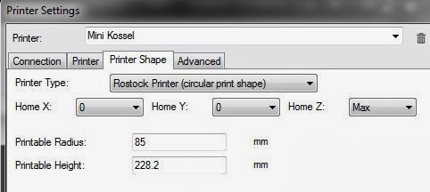
designing anything in particular. I made a toilet seat wrench, and a lampshade harp (the PLA sits on the LED light bulb to hold the shade), but mostly it's just stuff. So if that's your goal too, great. Now how big a thing do you want to print? Mendels typically have a 200mm by 200mm by 130mm build area. My mini Kossel is roughly (not accounting for the cone shapes at the top) 160mm diameter by 228mm tall. The biggest pieces I've printed are vases. But with a large print area comes a large footprint. I learned with my Mendel that I like to print one part at a time, not a whole sheet. The reason, if you have just one piece of a plate (a collection of 3D objects to print at one time) unstick, it can ruin all of them and if it happens late into a print...oh wow what a loss of time and material. Anyway, since I only print one object at a time, my actual build area is satisfied by the min Kossel. As a bonus, it fits on a relatively small wall shelf 16"wide and 12" deep. So I like the compactness. If you need/want bigger then look at the Kossel or Rostock, or Prusa i3.

  • Ok I picked a printer now what?
Well, you need to read everything you can about that printer. Find a forum that caters to your printer and start reading. Learn what people are having issues with (calibration is a big one) and try to find the answer. I'll most likely start a mini Kossel FAQ in a future post, my head is swimming with ideas and I'm not that fast a typist. Once you feel comfortable with that printer, it's BOM, and it's warts you need to plan your orders. It's not a bad idea to create a new forum post asking people to review your planned orders (unless you are using the stock BOM with known working part numbers) to see if the stepper motors will be suitable, power supply with work, etc.

  • I got my parts, is there a user guide on how to put this all together?
Maybe, maybe not. Hopefully this is something you find out in your process in identifying a printer model you like. For example, I knew I wanted to build a delta and there were 3 or 4 models to pick from 3DR, Kossel, Rostock, and the mini Kossel. When I saw that the mini used a linear rail guide
Linear rail guide
 that sealed the deal for me. Even though I had experience with the ball bushings and smooth rod, the mini Kossel just looked so simple and effective and the videos by Johann were very impressive, especially the auto-probe. I almost went with the 3DR, but I didn't like the idea of using Spectra, or having that much printed plastic as the frame of the machine. I also didn't want to look at roller guide like the Cerebus pup having to fiddle with tightening offset screws (my opinion, I have no experience with the v or w-wheels).

Again, those were my criteria, you may put a higher price on initial cost or potential maintenance. With the rails, you screw them down, grease the trucks and you are go there is nothing to adjust. The only thing I have not been impressed with is the auto-probe. I had it probing, but I couldn't tell it did anything, YMMV but I say leave it off your list and leave it off your printer.

mini Kossel belt tensioners
But I didn't answer your question. the mini is so straight forward I only needed to look at photos on Flickr to see what went where. the top printed pieces as belt tensioners was not obvious and I wasn't sure which screws were used where (I used 8mm screws on the rails at first for example), and I did need to remove some of the horizontal pieces to add nuts after I had the frame together. There is at least one online guide to use but you need to be prepared to adjust to what you have on hand unless you bought one of their kits. That's the nature of tinkering. Know up front you are on your own and you accept all responsibility for your actions (mistakes included). There is a large community and we foster a brotherhood and an eagerness to help so don't be afraid to ask before you do something you are unsure of. However, just because you "read it in the forums" you should confirm the source. Some people are so eager to "give back" that they don't always check their facts (hearsay) or don't speak from direct experience...asker beware.

  • Ok, it's together, now how do I wire it up?
RAMPS 1.4
Ok, well now we are getting into a forest of trees. There are so many electronics options and I said I only speak from personal experience so I am only going to talk from the Arduino/Ramps perspective.wiring diagram and familiarize yourself with the components. For a the most basic delta you will have 4 stepper motors and drivers, 3 endstops (connected to the MAX inputs and I'm leaving the probe off), a 12 volt power supply, a hotend heater and a hotend temperature probe. I think it's a bit too low level to discuss extending your wires on your stepper or how to solder wires on here, but if I'm wrong, let me know I can can add it. You will need to decide where your controller will be. I put mine at the top and ran the towers stepper wires up to it. Your choice, but you want it some place where you can put a cooling fan on the stepper drivers. Scroll down to where I get into more details below.

Some of what I talk about is the same for other boards so I think there is still broad value in what I'll write. So the first thing is to find the

DRV8825 Stepper driver board
Stepper drivers from Pololu will either be 4988 or 
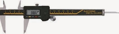
8825. Both have a current limit variable resistor (aka pot or potentiometer) that you will need to calibrate before you go much further. This is a fiddly procedure and having a helper with good eyes and a steady hand will help, though I did it by myself. Here is a good write up of the process (http://www.indigent-networks.com/pololu-drivers-current-limit-configuration/).

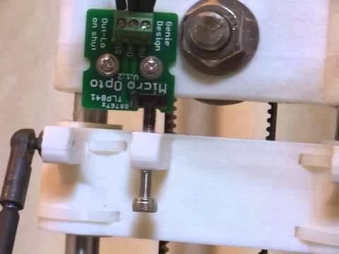
The simplest endstop is a mechanical switch. Some people like to jazz it up and add a LED or use opto interrupters or seems like hall effect sensors and magnets are in vogue...I say KISS (keep it simple) and use a bare microswitch with or without a lever it doesn't matter. Connect one wire to the NO (normally open) lead and one wire to the C (common) lead and connect the wires (doesn't matter which to which pin) to the S (signal) and -(read as minus or negative which is the same as Ground) pins on the RAMPS endstop header. Do not connect to + and - or you will short 5V to ground whenever your endstop is triggered (not good). Because we connected the endstop to NO, then the signal on the input will use the internal pull up to read greater than than 3.5V  or logic 1. When the switch is tripped, the signal is grounded to 0V or logic 0. I think it's important you know why we did it this way and what to expect. Of course you can also use the NC (normally closed) and C (common) instead. This time the voltage will be 5V when not triggered (logic 1), so you would need to invert the logic in your configuration.h. The mini Kossel instructions call for it to be this way...but it doesn't matter since the logic can be flipped in firmware.

Arduino 
Now we need to get into Arduino. Some sellers pre-load firmware on the board, but there is no guarantee it'll match your configuration and may not be the latest version. In any event, you need to know how to load firmware. With the Arduino Mega/RAMPS is simple, I can't speak for other controller options. Since this is the basics, we'll start from scratch and download the Arduino software. And run through the Getting Started to understand the flow. On Windows the hardest thing is getting the USB driver installed, hopefully you have administrative rights ;) If you can upload blink then you can upload reprap firmware. If not, keep trying until you can. On, now we need the firmware. I prefer the main branch of Marlin. Most reprap project use github to distribute and track changes in their software. It also allows other to contribute and fork (make their customized versions) of the software. In this case Johann forked marlin, added his delta code to it, and the author Erik Zalm pulled Johann's code into the main branch. You can see how active development is on Marlin is by looking at the network graph. A lot of people have contributed.

Firmware
Github download button
For now we just want to download the main branch. Look in the lower right corner of the page and find the Download ZIP button.
This will save a zipped copy of the project to your computer. Personally I create a sub-directory under where I installed my Arduino software called reprap firmwares and unzip the contents into there. That way I can keep older copies of known working configurations. Wherever you unzip the files to, you should have a folder/directory structure like this:
  • Marlin   - this is the main/parent directory
    • example_configurations
      • delta
There are two files in delta that we need to copy to the Marlin parent directory. Go ahead and overwrite the existing configuration.h and configuration_adv.h files, they are for non-deltas. If you are using these as a guide for non delta, then skip this step :) So the first item of business is to specify your controller. Open up Marlin.pde (or .ino) in the Arduino software. This will open up all the project files too. Find the Configuration.h file and let's begin.

Configuration.h

  1. You need to specify your MOTHERBOARD. This is another name for your controller and since we are using a RAMPs v1.4 we would set #define MOTHERBOARD 33. This lets the software know what pins on the AVR Mega (the microcontroller at the heart of our Arduino mega board) are mapped to what peripheral (endstops, step and direction pins on the stepper drivers, MOSFET outputs for the heater and fan, etc. Just a note, if you see a double slash like this // on a line, it means that line of code it commented out. 
  2. Now you need some physical measurements from your machine. Values are for my machine, yours will vary I'm sure. Also, I won't even try to explain what all of these mean or do, I honestly don't care and if you do, this is way too basic a place to put that level of discussion in play.
    • #define DELTA_DIAGONAL_ROD 215.0 // Center-to-center distance of the holes in the diagonal push rods. If you bought yours it's reasonable to assume they are all the same length that you ordered. If you assembled them yourself, and you used a jig you can assume the same thing. However if even with careful planning and execution you ended up cutting on the wrong line...well then make sure to measure.
    • #define DELTA_SMOOTH_ROD_OFFSET 144.55 // mm Horizontal offset from middle of printer to smooth rod center. This will be the value you will need to adjust during calibration
    • #define DELTA_EFFECTOR_OFFSET 19.9 // Horizontal offset of the universal joints on the end effector. This is the distance from the some reference point (say the face of the 1515 extrusion) to the pivot of the diagonal rod where it connects to the carriage. Why it's19.9mm instead of 19.5mm I'm not sure, because the height of the "Hiwin" rail and truck is 13mm and the half height of the carriage is 13/2 or 6.5mm so 19.5mm
    • #define DELTA_CARRIAGE_OFFSET 19.5 // mm - This one comes from the SCAD file and is the distance from the center of the effector to the diagonal rod pivot point.
The reason I say you can ignore these is because all we really want is the delta radius. The horizontal distance from the center of the effector to the pivot on the carriage. So you'll see the line
#define DELTA_RADIUS (DELTA_SMOOTH_ROD_OFFSET-DELTA_EFFECTOR_OFFSET-DELTA_CARRIAGE_OFFSET). What good is the DELTA_RADIUS you say, well, that is how the firmware will map a Cartesian coordinate pair (X, Y) to a delta coordinate pairs. Here is a sample:

Looking at the delta layout image, imagine yourself looking down from the top of the delta printer with the X and Y towers in the front left and right positions and the Z tower in the middle back. c is the center point and the distance from c to any of the x, y, or z (note the lower case) points is DELTA_RADIUS. In a delta, c is (0,0) with an imaginary horizontal x-axis line passing through c in the positive and negative direction. Similarly there is an imaginary vertical line through c representing the y-axis. 
Delta layout
I know you are asking, why would you use X, Y, and Z for the tower names when x,y are the coordinate names and it's confusing to me when you say the X tower is at (-x,-y)? Well, the best reason I can think of is that reprap started wit Cartesian bots and the axis motors are labeled X, Y, and Z on the RAMPS. I agree it would be better to call them A, B, C or Alpha, Beta, Gamma, or anything else :)

I digress. So looking at the X-Y grid below notice how the x values decrease as you move to the left (negative to the left of the y-axis) and increase as you move to the right (positive to the right of y-axis. Same for the y values decrease as you move down (negative to the below the x-axis which is to the front of your machine) and increase as you move up (positive above the of x-axis which is to the rear of your machine. So at a high level we can say that the point x in the delta layout image is some negative x value and some negative y value (-xi, -yi) or to the left and front of the center point c. For point y it would be (xi,-yi) and for point z (0,y). Zero for x? Yep, it's on the axis line and remember our center is (0,0).

Now how do we calculate the x and y coordinates of these three points? Trigonometry, or triangular math. If you don't want to know or don't care, skip this step, it's going to use sine and cosine and some multiplication. There is a working radius where your effector can travel in a complete circle without hitting anything we'll call this radius R and for the mini we'll use 80mm. This means that the diameter of our circle is 160mm (you can use 85 and get 170 if you like too) and or x and y max values are -80 to 80 on the x and y axis, but not on the diagonals for the X (alpha) or Y(beta) towers. You know there are 360 degrees in a circle. If we take some point on the x-axis and rotate it counter clockwise 90 degrees that point would now be on the y-axis. It we rotate it another 90 (180 total) it would be on the x-axis but on the negative or left side of the y-axis. Another 90 (270 degrees total) and we are on the y-axis in the negative region. And one more 90 (360 degrees) and we back where we started (full circle). Deltas are equidistant from one another or 360/3 = 120 degrees apart. Since the Z(gamma) tower is on the y-axis it's at 90 degrees...with me so far? So now if I add 120 degrees to 90 then we are at 210 degrees for the X(alpha) tower and 310 for the Y(beta) tower.

So now let's convert polar coordinates Ri at angle theta to Cartesian (x,y). For X tower we have Ri = DETLA_RADIUS and for point x in front (with the notion that the towers face inward to the center point c) of tower X(alpha) being 80mm and it's angle theta =210 degrees, (x=cos(theta)*Ri, y=sin(theta)*Ri). So we get point x coordinates= (-69.282, -40). Similarly for Y(beta) tower where theta is 310 we have (69.282, -40). Finally for tower Z(gamma) we have (0, 80).

Um ok, but what does this have to do with the editing of the configuration.h editing we were doing? 
Yeah you caught me, I dove into the details a bit so getting back on track you'll need to find and set:
 // Travel limits after homing
 #define X_MAX_POS 90    // note how 90 is the default. You can make this 80 or leave it 90 for the mini, this is a "soft limit" and the firmware will not let you go to (110,110) if you set the max to 90 for both.
 #define X_MIN_POS -90
 #define Y_MAX_POS 90
 #define Y_MIN_POS -90
 #define Z_MAX_POS MANUAL_Z_HOME_POS // This one is important and you need to find the #define for MANUAL_Z_HOME_POS further down
 #define Z_MIN_POS 0

 #define MANUAL_HOME_POSITIONS  // MANUAL_*_HOME_POS below will be used
 // For deltabots this means top and center of the cartesian print volume.
 #define MANUAL_X_HOME_POS 0
 #define MANUAL_Y_HOME_POS 0
 #define MANUAL_Z_HOME_POS 250 // For delta: Distance between nozzle and print surface after homing.  This is a measured value, and can change depending on your hot end length, your vertical extrusion lengths, and where your end stops are mounted.

Finally enable the EEPROM by ensuring the following two lines are uncommented
#define EEPROM_SETTINGS
#define EEPROM_CHITCHAT

Temperature sensors
You have to define TEMP_SENSOR_0 no if's, and's or but's. If you don't, the firmware will throw an error when you connect with your host software. the same thing will happen if you do not connect or have an open circuit to your actual thermistor, it's a safety feature. Use the chart of known thermistors and pick the one that matches. I don't use a heated bed, but if you do, then define the TEMP_SENSOR_BED too.

End stops
Micro switch
If you are using mechanical end stops like me, then you are going to wire them normally closed (NC). This means the switch connects the NC terminal to the C (common) terminal until the switch plunger is depressed. The two wires go back to the RAMPS and connect to the end stop headers. One wire connects to - (aka minus, negative, GND or Ground) and the other to S (signal). S then connects to a physical pin on a AVR microcontroller pin. If look at the digital logic that this pin sees based on the voltage present on this pin, it would be 0V when the switch is not depressed (not homed) because it's connected to ground, and not connected to anything (open) when it is depressed. If the circuit is open the voltage on the MCU pin will float unless we pull it up to a high voltage (5V). To do this we need to to ensure #define ENDSTOPPULLUPS is uncommented. #define _MAX_ENDSTOP_INVERTING are set to false.
End stop header on RAMPS
Note: X+ is to the right of X- some for Y and Z

This tells the AVR to connect all of the end stop pins internally to Vcc (5V) via an internal resistor to limit current. If you are using a different endstop (opto, hall, etc..) then you may not need this internal pullup resistor. Using typical digital logic, 0 volts equals a logic 0 (aka false) and 5V (Vcc) = a logic 1 (aka true). So right now, if we do nothing else, then we would see false when the switch is not depressed and true when it is. So we don't need to invert the logic. You will need to make sure all of the [x,y,z,min,max]_ENDSTOP_INVERTING = false in your configuration.h.

Steps per unit
You need to tell the firmware how many steps it needs to send tot he stepper driver to move the carriage 1 mm. There are calculators that you can use to get this,= but if you are using 1/16th microstepping drivers, GT2 belts, and 16 tooth pulleys you would enter 100 for the X, Y, and Z motors. If you have 1/32 microstepping then you would use 200.
 #define DEFAULT_AXIS_STEPS_PER_UNIT   {100,100,100,506}
The last number is specific to your extruder and in my opinion should be directly measured by following this calibration guide.

See my new post on Wiring and soon First Test and calibration